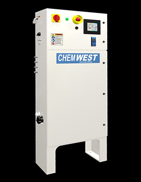
CONDUCTIVITY CONTROL SYSTEM (CCS) OVERVIEW
The Chemwest Conductivity Control System (CCS) has been designed to continuously adjust the amount of CO2 injected into an ultrapure water (UPW) stream to achieve the targeted conductivity. Changes in the UPW flow rate are not a problem for the CCS. Closed-loop control based upon conductivity is used to ensure the conductivity is maintained even as the flow rate changes rapidly.
The system uses membrane contactor technology to provide bubble-free injection of the CO2. An all fluoropolymer flow path is used to maintain the purity of the DI water and prevent the introduction of particles or contaminates.
The CCS operates in a wide range of UPW flow rates and conductivity levels providing the flexibility to meet an array of application requirements.
APPLICATIONS
- Wet Etch Clean (WEC) critical rinses
- Extreme Ultraviolet Lithography (EUV) mask cleaning
- Photolithography reticle cleaning
- Photolithography spin-rinse process
- Post Chemical Mechanical Planarization (CMP) rinse process
- Photoresist residual removal
PROCESS BENEFITS
IMPROVED YIELDS
PRE IMPROVEMENT
The use of low conductivity UPW during the wafer rinsing process prevents the dissipation of wafer surface changes that may be present on the incoming wafer or generated during the rinse process. Particle attraction and adhesion to the wafer surface can result in yield limiting defects. Adding CO2 to UPW during the rinse process will help to reduce the surface charge and may allow for the release of these defect causing particles1 from the wafer surface.
ESD DEFECT REDUCTION
Static buildup on the wafer surface during the wafer rinse process can occur if low conductivity UPW is used. Catastrophic wafer defects due to electrostatic discharge (ESD) have been reported as a result of this static buildup during spin rinse processing.2 Increasing the conductivity of the UPW rinse water through the use of CO2 injection can significantly reduce this type of defect.
CORROSION CONTROL
Corrosion of metal lines (Cu, Al) can occur during the UPW rinse process that follows resist/polymer removal with amine based chemistries. This is due to the creation of hydroxyl ions when the water interacts with the hydroxyl amines. The addition of CO2 into the UPW rinse water neutralizes the hydroxyl ions preventing this metal corrosion from occurring.3
1 Harumoto, M. et al., "Post-Develop Blob Defect Reduction", SPIE Advanced Lithography 2009, Conference Proceedings Paper. http://spie.org/x648.xml?product_id=8136052 Halladay, J. et al., "Elimination of ESD Defects Using DICO2", SEMATECH Surface Preparation and Cleaning Conference, March 31-April 2, 2008 http://qcepttech.com/documents/0210HalladaySpansion.pdf
3 Gu, M. et al., "An Improved Wet Cleaning Method for 90nm Node- Semiconductor processing Technology", Future Fab Intl., Issue 18, Jan. 12, 2005 http://www.future-fab.com/documents.asp?d_iD=3028
FEATURES AND BENEFITS
| Features | Benefits |
|---|---|
Automatic Conductivity Control |
High performance, high precision closed loop conductivity control ensures optimum process stability and maximizes process window |
Direct Injection Gasification Method |
Delivers a stable conductivity CO2 / UPW mixture with low gas consumption and simple system design and control with no bubble generation |
Programmable Maintenance |
Automatic maintenance of membrane contactor ensures optimum gas transfer efficiency and minimum downtime |
Visual Human/Machine Interface software |
Visual touchscreen software allows simple setup and programming of process conditions |
Embedded Communication |
Analog and digital output to customer tool and remote control by customer tool through industry standard connectors and protocols. Provides connections via Customer Ethernet for data logging / monitoring functions |
Safety Alarms, Sensors |
Process parameter alarms and system leak sensors ensure process and machine safety |
Membrane Technology |
Unique membrane reduces gas usage and ensures low Cost of Ownership |
SPECIFICATIONS
System flow range |
1-60 L/min (1) |
|
Conductivity range |
0.5 – 40 µS/cm2 (2) |
|
Transient stability |
± 5% of setpoint |
|
Steady State Stability |
± 2% of setpoint |
(Dependent upon incoming UPW flow stability) |
UPW requirements |
Pressure Range |
0.21 – 0.48 MPa (30-60 PSIG) |
Max Temperature |
40°C |
|
CO2 requirements |
Pressure Range |
0.2 – 0.7 MPa (30-100 PSIG) |
Minimum Purity |
Grade 4 |
|
N2 requirements |
Pressure Range |
0.15 – 0.7 MPa (20-100 PSIG) |
Minimum Purity |
Grade 2 |
|
CDA requirements |
Pressure Range |
0.5 – 1.5 MPa (75-215 PSIG) |
Electrical requirements |
120 vac, 60 hz, 1 ph |
FLA 5.1A, Max. 10A |
Box Dimensions (Maximum; No Ftgs) |
Standard System |
Height-57", Width-24", Depth-12" |
2 Conductivity range is dependent upon UPW flow range and temperature. Each system is shipped tuned for target conductivity setpoint and flow range. Please consult Chemwest for your specific requirements.
3 System requires a minimum of 200mm (8") above and 200mm (8") below the unit to allow facility connections.


